Display Management System (DMS) Support
Overview
Display Management System (DMS) is a screen warp, blend, and color correction interface from FlightSafety. DMS provides calibration data to Nova to conform the output from projectors to the screen being used in the simulation. It uses the Nova internal calibration configuration along with specified warp ".tif" files to render the warping. In addition, the DMS system allows for runtime changes to the warping of the system via commands sent directly to the DMS via a port specified within the configuration.
Setup
DMS requires three tokens to set up the warping configuration which can be located within your cluster.cfg or override configs when running standalone and within your frontend configuration when running a cluster configuration. Below are the tokens required:
Token | Value | Use |
|---|---|---|
CalibrationMode | INTERNAL | Automatic display Calibration/Warping mode specified for rendering. Internal setting represents a DMS configuration. |
CalibrationDir | STRING | Directory containing images for Internal calibration |
CalibrationConfig | STRING | Additional per-channel parameters related to display calibration. |
The "CalibrationConfig" configuration file also contains it's own set of configuration tokens detailed below:
NOTE: * denotes the channel number to apply the warping to.
Token | Value(s) | Use |
|---|---|---|
DMS_PORT | INT | Specifies port for receiving commands for runtime warp changes. |
CH*_NAME | STRING | Name of the channel to apply warping to. |
CH*_ID | INT | Identification number designating how the channel will be indexed internally. |
CH*_OUTPUTS | INT | Number of displays being rendered to. |
CH*_FBO_SIZE_X | INT | Frame buffer object resolution size along X axis. |
CH*_FBO_SIZE_Y | INT | Frame buffer object resolution size along Y axis. |
CH*_INVERT_OUT_X | ON/OFF | Invert the FBO output along the X axis. |
CH*_INVERT_OUT_Y | ON/OFF | Invert the FBO output along the Y axis. |
CH*_RESAMPLE_ONLY | ON/OFF | Enable/disable resampling only. |
CH*_AUTO_MIPMAP | ON/OFF | Enable/disable auto mipmap option. |
CH*_DISTORTION_MAP_MODE | ABSOLUTE/OFFSET/OFF | Mode specifying the mapping configuration to the FBO. |
CH*_DISTORTION_MAP_FILE | INT and STRING | Configure eyepoint and warp file to be used located within the CalibrationMode directory. |
CH*_DISTORTION_MAP_WIDTH | INT | Distortion map resolution size along the X axis. |
CH*_DISTORTION_MAP_HEIGHT | INT | Distortion map resolution size along the Y axis. |
CH*_LUMINANCE_MAP_MODE | DISTORTION_BLUE_CHANNEL/INDEPENDENT/OFF | Mode specifying the luminance configuration to the FBO. |
CH*_LUMINANCE_MAP_FILE | INT and STRING | Specifies eyepoint and luminance file to be used located within the CalibrationMode directory. |
CH*_LUMINANCE_MAP_WIDTH | INT | Luminance map resolution size along X axis. |
CH*_LUMINANCE_MAP_HEIGHT | INT | Luminance map resolution size along Y axis. |
CH*_BLACK_LEVEL_MAP_FILE | INT and STRING | Specifies eyepoint and black level file to be used located within the CalibrationMode directory. |
CH*_GAMMA_FILE | STRING | Specifies a gamma file to be used. |
CH*_DYNAMIC_WARP_UPDATES | ON/OFF | Allow for runtime updates to the warping. |
Running DMS and Real-Time Commands
Start Nova with the appropriate configurations found within the setup and run Nova normally and the warping should appear on startup. If issues arise during setup information on configuration is usually printed to the command window.
With DMS there is the capability to make runtime changes to the warping via a TCP connection using the specified port within the configuration specified in the "CalibrationConfig" token. Below is a breakdown of the commands that can be sent/received using this interface:
Communication Protocol
Communication between the alignment system and DMS requires the following structure:
Start | 1 byte |
Command Code | 1 byte |
Data Mode | 4 bytes |
Data Length | 4 bytes |
Data | N bytes |
The reply from a write command is a 32-bit signed integer. Negative values indicate errors. Positive or zero values indicate success.
The reply from a read command takes on the following format:
Data Length | 4 bytes |
Data | N bytes |
Byte order is big-endian.
Command Set
Load Test Pattern
Command
Start | 0x53 |
Command Code | 0x1d |
Data Mode | 0x00 Zero-based channel ID 0x01 0x00 |
Data Length | Length of data (bytes) |
Data | ASCII string containing path/filename of desired test pattern. String terminator is required. |
Reply
Data Length | 0x00 0x00 0x00 0x04 |
Data | 32-bit signed integer status |
Unload Test Pattern
Command
Start | 0x53 |
Command Code | 0x1d |
Data Mode | 0x00 Zero-based channel ID 0x01 0x00 |
Data Length | 0x00 0x00 0x00 0x00 |
Reply
Data Length | 0x00 0x00 0x00 0x04 |
Data | 32-bit signed integer status |
Test patterns are tiff images. Test patterns will be warped and color-corrected in the same manner as the rendered image.
Set Test Pattern Illumination
Command
Start | 0x53 |
Command Code | 0x24 |
Data Mode | 0x00 Zero-based channel ID 0x69 0x6c |
Data Length | 0x00 0x00 0x00 0x0C |
Data | Red Value Green Value Blue Value |
RGB Values are single precision floats in the range of 0 to 1
Reply
Data Length | 0x00 0x00 0x00 0x04 |
Data | 32-bit signed integer status |
Get Test Pattern Illumination
Command
Start | 0x53 |
Command Code | 0x23 |
Data Mode | 0x00 Zero-based channel ID 0x69 0x6c |
Reply
Data Length | 0x00 0x00 0x00 0x0C |
Data | Red Value Green Value Blue Value |
RGB Values are single precision floats in the range of 0 to 1
Set Edge Mask
Command
Start | 0x53 |
Command Code | 0x24 |
Data Mode | 0x00 Zero-based channel ID 0x65 0x62 |
Data Length | 0x00 0x00 0x00 0x04 |
Data | 0x00 0x00 0x00 0x00 (disable) or 0x01 (enable) |
Reply
Data Length | 0x00 0x00 0x00 0x04 |
Data | 32-bit signed integer status |
Get Edge Mask State
Command
Start | 0x53 |
Command Code | 0x23 |
Data Mode | 0x00 Zero-based channel ID 0x65 0x62 |
Reply
Data Length | 0x00 0x00 0x00 0x04 |
Data | 0x00 0x00 0x00 0x00 (disabled) or 0x01 (enabled) |
Set Edge Blends
Command
Start | 0x53 |
Command Code | 0x24 |
Data Mode | 0x00 Zero-based channel ID 0x78 0x62 |
Data Length | 0x00 0x00 0x00 0x04 |
Data | 0x00 0x00 0x00 0x00 (disable) or 0x01 (enable) |
Reply
Data Length | 0x00 0x00 0x00 0x04 |
Data | 32-bit signed integer status |
Get Edge Blends State
Command
Start | 0x53 |
Command Code | 0x23 |
Data Mode | 0x00 Zero-based channel ID 0x78 0x62 |
Reply
Data Length | 0x00 0x00 0x00 0x04 |
Data | 0x00 0x00 0x00 0x00 (disabled) or 0x01 (enabled) |
Set Eyepoint Selection
Command
Start | 0x53 |
Command Code | 0x24 |
Data Mode | 0x00 Zero-based channel ID 0x72 0x63 |
Data Length | 0x00 0x00 0x00 0x04 |
Data | 32-bit signed eyepoint index |
Reply
Data Length | 0x00 0x00 0x00 0x04 |
Data | 32-bit signed integer status |
Get Eyepoint Selection
Command
Start | 0x53 |
Command Code | 0x23 |
Data Mode | 0x00 Zero-based channel ID 0x72 0x63 |
Reply
Data Length | 0x00 0x00 0x00 0x04 |
Data | 32-bit signed eyepoint index |
The eyepoint selection causes an alternate warp map to be applied to the image.
Refresh render
Command
Start | 0x53 |
Command Code | 0x24 |
Data Mode | 0x00 Zero-based channel ID 0x72 0x63 |
Data Length | 0x00 0x00 0x00 0x04 |
Data | 0x00 0x00 0x00 0x01 |
Reply
Data Length | 0x00 0x00 0x00 0x04 |
Data | 32-bit signed integer status |
A refresh causes a reload of all corrections to the channel.
Get System Status
Command
Start | 0x53 |
Command Code | 0x23 |
Data Mode | 0x00 Zero-based channel ID 0x73 0x74 |
Reply
Data Length | 0x00 0x00 0x00 0x04 |
Data | 32-bit signed integer status |
System status is used as a connection check and to provide general-purpose status.
Runtime Communication
A secondary connection is made to facilitate runtime updates from DMS. This connection follows a different protocol than the control channel.
Start Runtime Service
Command
Start | 0x53 |
Command Code | 0x37 |
Reply
Command Code | 0x44 0x01 |
Data | Desired black level Minimum luminance |
Once the service is started, replies are sent unsolicited with time of day changes. Desired black level is a single-precision float indicating the level of darkness desired for the time of day. Minimum luminance is a single-precision float indicating the lowest allowable brightness for the time of day. If the contrast of the system does not permit both requests to be met, the minimum brightness takes precedence over desired black level.
Example
Nova overrides:
CODE
|
CalibrationConfig file settings:
CODE
|
Example Warp Files:
Example Test Pattern File:
Testing
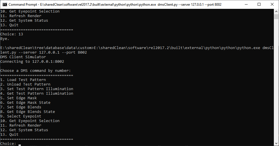
To fully test the DMS interface, a Python script can be run that allows for runtime changes to the configuration. The script is constructed in python and requires it to run. Simply run python.exe from the command line and input the script "dmsClient.py" as an argument. The interface is fairly straightforward with commands for loading/unloading different pattern types, setting various edge states, selecting eyepoints and getting the current DMS state. One important note when specifying a new test/illumination pattern, path location should be relative to the "CalibrationDir" directory.
CODE
|