The following sections outline the specifics on each of the Nova Host’s capabilities and how to use them.
Ownship Control
The Ownship Control tab allows you to control the position of the ownship, Adjust the visual model and special effects, and see the IG returns for the ownship.
Flight Controls
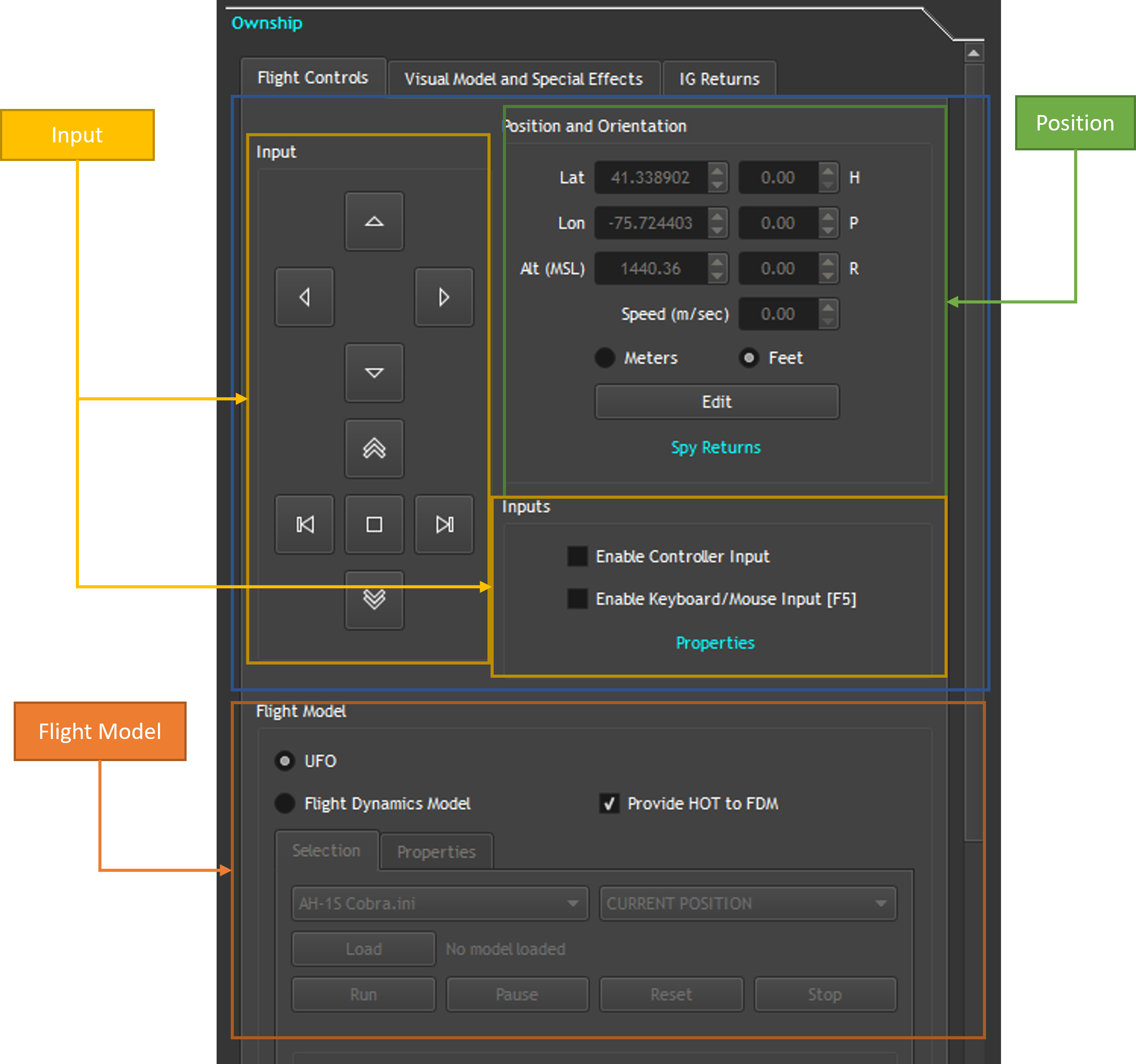
The Flight Controls tab allows you change the ownship’s position, orientation, as well as use a dynamic model to control the ownship.
Inputs
The Input box acts as an on screen controller for the ownship. The upper 4 arrows will adjust the heading and pitch of the ownship. The lower 4 arrows act as directional input into the ownship The Inputs box allows you to change the input source for the ownship. You can either control it with a Xbox controller or use the keyboard and mouse. The properties button will allow you to see the configuration for each input option, GUI, keyboard, controller.
Position And Orientation
The position and orientation box will allow you to change the ownship’s position and orientation directly. To enable the input boxes click on the “Edit” button. When the input boxes are active, the inputs will not work and will be overwritten.
Flight Model
The flight model box gives you the option to control the ownship as a UFO or as a dynamic model. To enable the dynamics model select the “Flight Dynamics Model” radio button. To select a model, pick one from the first drop down, select a location from the second drop down, and click on “Load.” This will place the ownship at the selected location if not using the current position. After loading the model, click on “Run”. To stop the model, click on “Stop.”
Visual Model and Special Effects
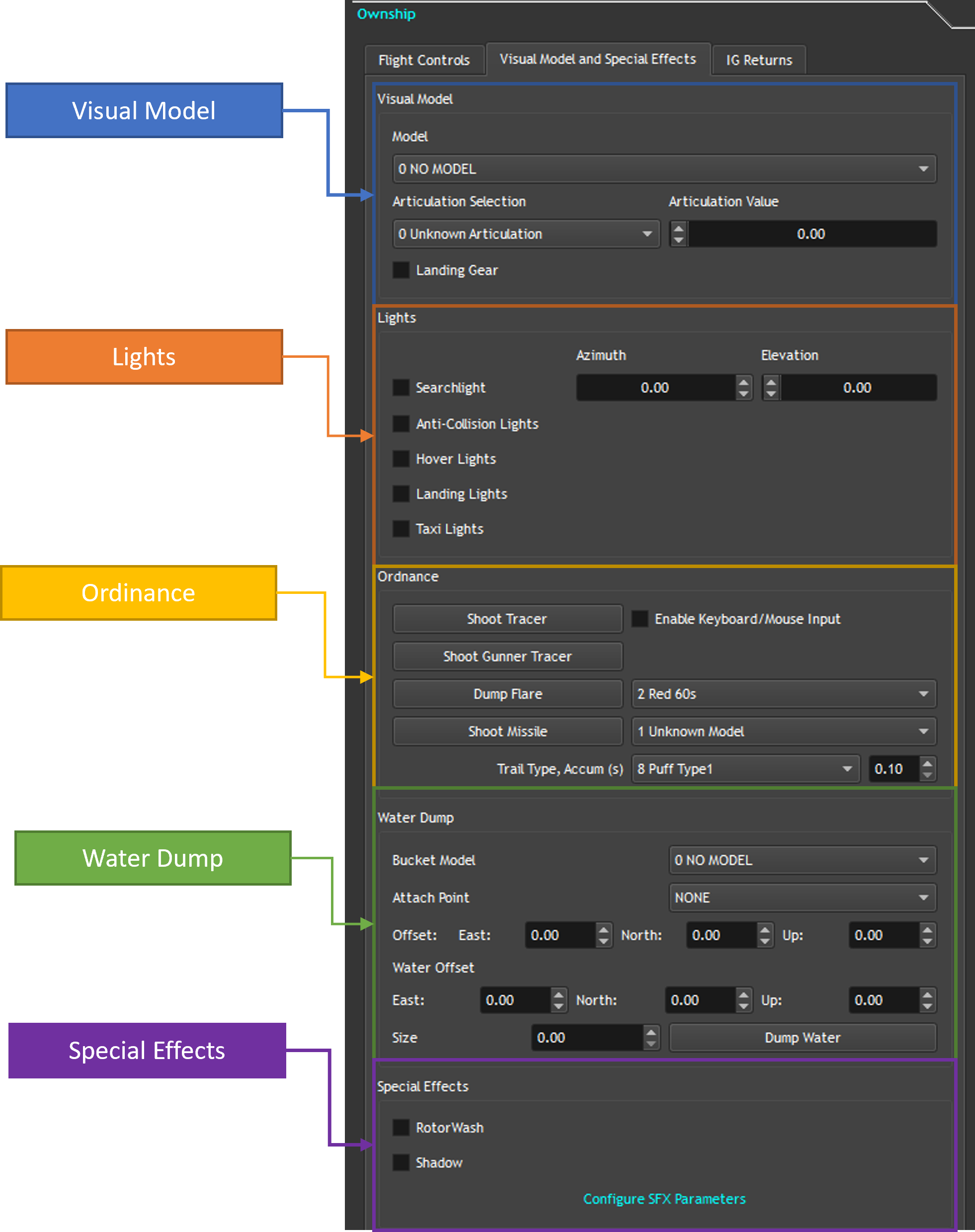
The visual model and special effect tab allows you to change the current ownship model for the ownship as well as control any articulations for that model.
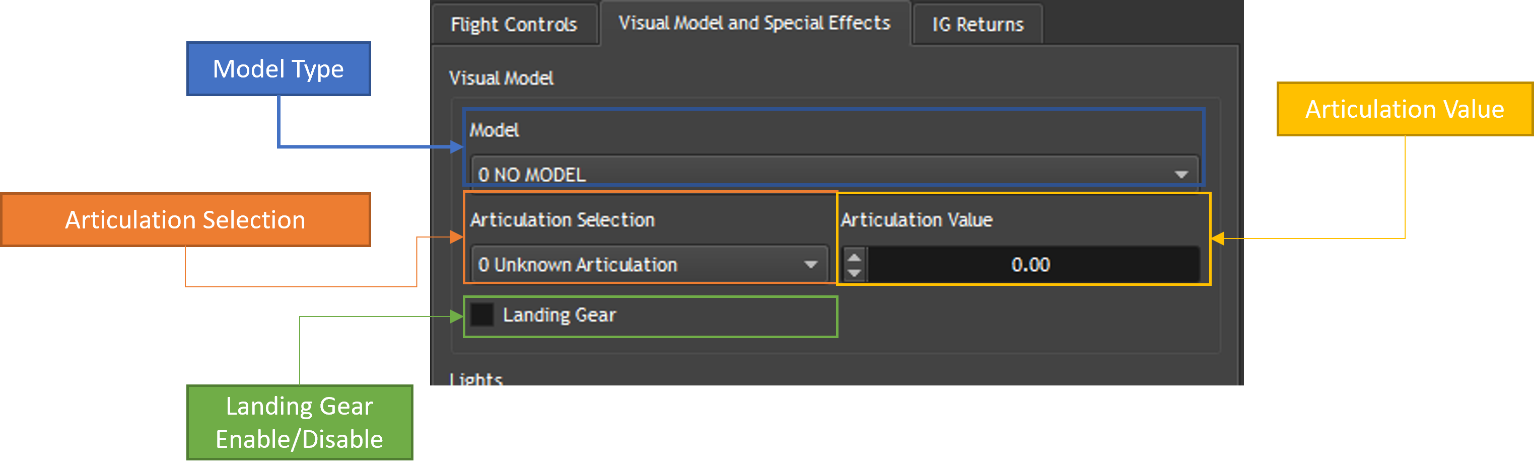
Visual Model
The Visual Model options allow you to change the model that the ownship is using, as well as changing different articulation values. To change the model that the ownship is currently using, simply select a model from the dropdown. To change an articulation and the value for that articulation, select the articulation from the dropdown and adjust the value in the “Articulation Value” input.
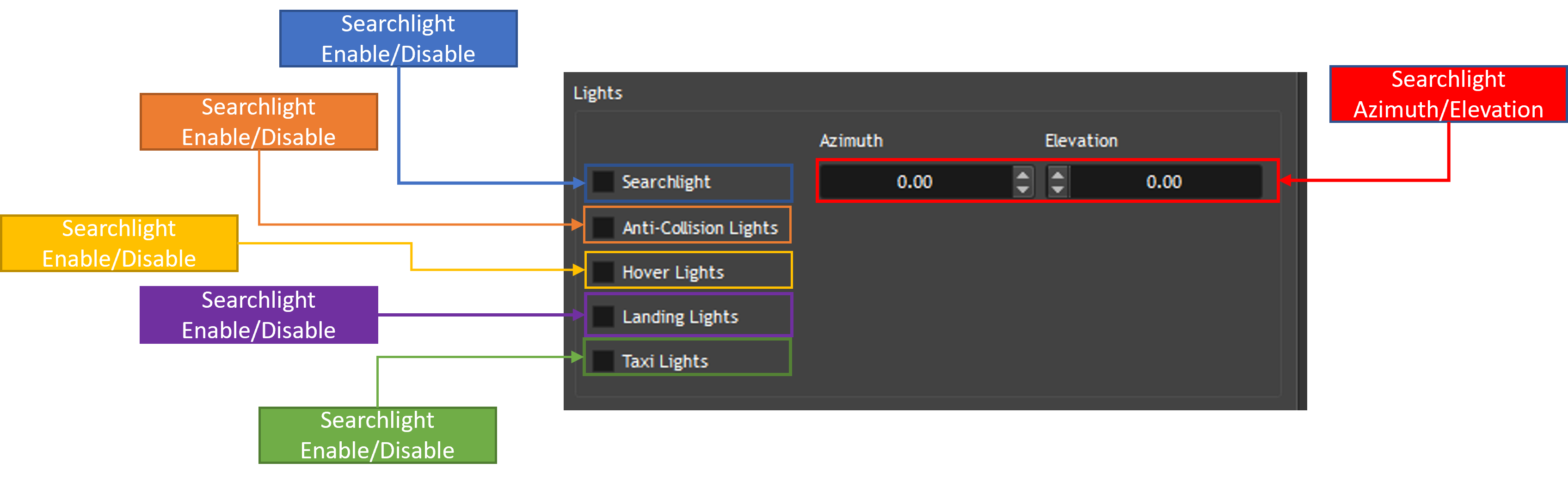
Lights
The Lights options will allow you enable/disable lights on the ownship and change the azimuth/elevation for the searchlight.
Ordinance
To use tracers/missiles/flares press the buttons in the “Ordinance” box. To change what type of flare is deployed, select one of the flares from the drop down and click on “Dump Flare” If nova has missiles loaded, they will show up in the drop down next to the “Shoot Missile” button. To change what type of missile is fired, select one of the options from the dropdown. The trail type for the missile can be changed from the dropdown next to “Trail Type, Accum (s)” as well as the duration for the trail type.
Special Effects
To enable/disable special effects for the ownship check/uncheck the “Rotor Wash” and “Shadow” checkboxes. You can also adjust the parameters for the rotor wash by clicking on “Configure SFX Parameters.” The values will be brought up in the Spy tab. See section X.X for the Spy tab.
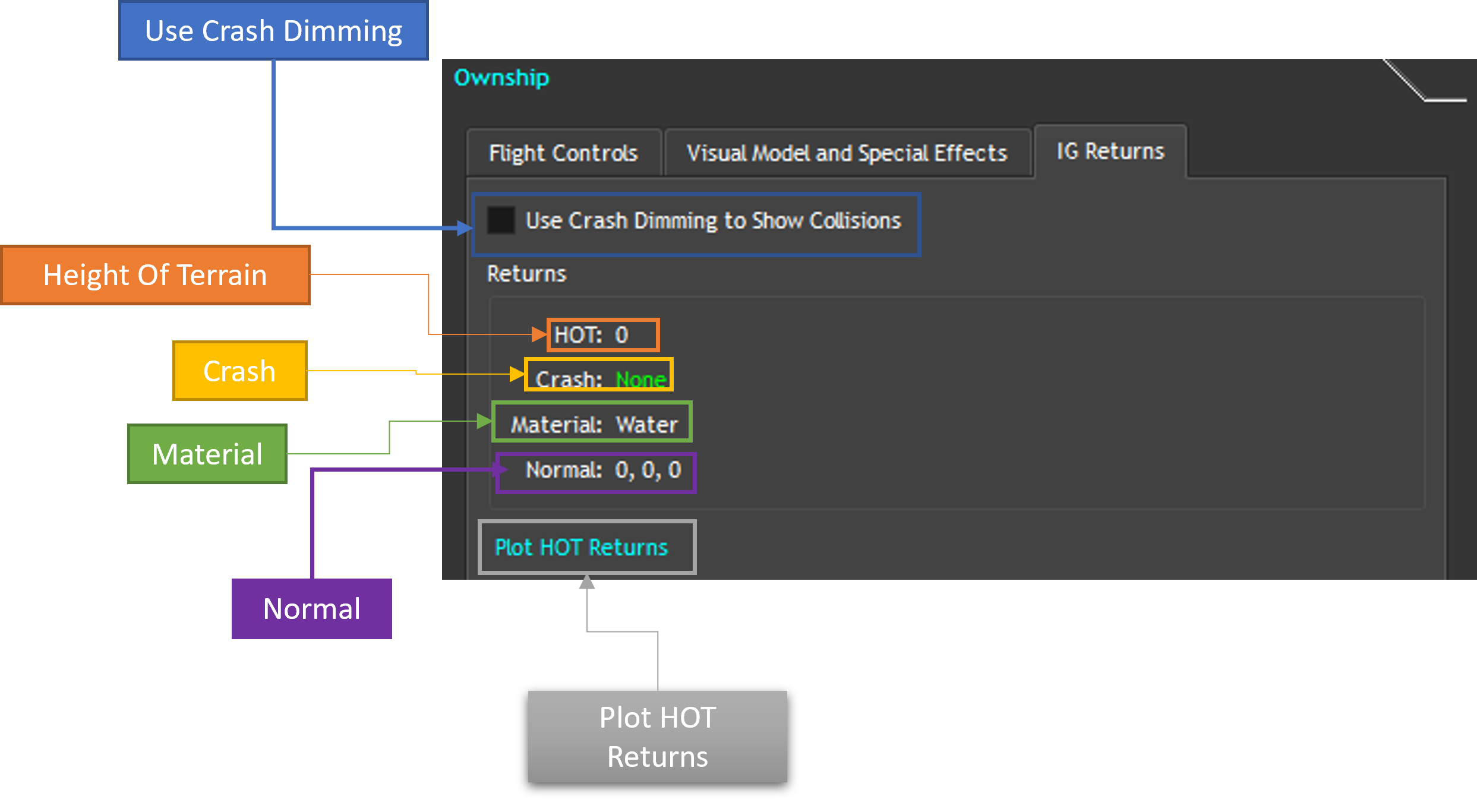
IG Returns
The IG Returns tab shows the return data for the ownship. The returns contain the height of terrain, if the ownship is colliding with the terrain, building, or target, the type of terrain, and the normal. You can enable Crash Dimming to indicate on the IG if it has collided with something.
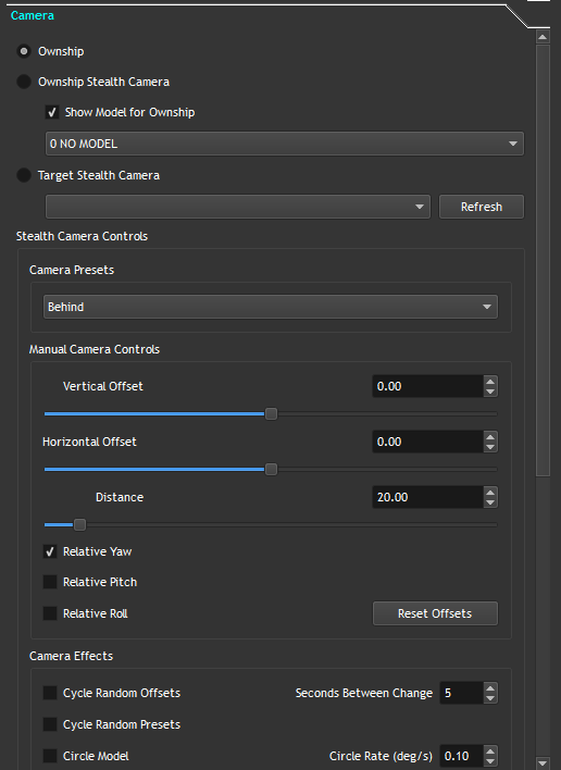
Camera Control
The Camera Control tab allows you reposition the view to either the ownship, the stealth ownship, or an active target.
Camera Target Options
To switch between what the camera is attached to, switch between the Ownship, Ownship Stealth Camera, and Target Stealth Camera. The Ownship Stealth Camera will allow you to place a Stealth Ownship in the scene. The Target Stealth Camera will allow you to select different Targets in the scene, if created in the Targets Control, see Section 3.3.
Stealth Camera Controls
3.2.2.1. Camera Presets
There are a number of presets to position the camera about the selected target. To change a preset select one from the Camera Presets dropdown
3.2.2.2. Manual Camera Controls
You can also adjust the camera offsets manually by either adjusting the sliders or entering a value in the input boxes. Vertical offset will adjust the view about the pitch of the target, horizontal offset will adjust the view about the heading of the target, if Relative Yaw is selected, and Distance will adjust how far the camera is from the target.
3.2.2.3. Camera Effects
The Camera Effects options allow you to cycle through random offsets or presets. To cycle between random offsets, check Cycle Random Offsets and the offsets will change every N second(s) where N is the number of seconds set in Seconds Between Change. You can also have the camera circle a model by checking Circle Model and the rate at which it will circle the model is set in Circle Rate (deg/s). The camera can also be animated to go up and down about the target/ownship. To enable this, check Vertically Animate. The minimum and maximum offsets can be set in Min, Max offset (deg).
3.2.2.4. Camera Offsets
To adjust the absolute offsets for the camera, the sliders in the Camera Offsets box can be used. From here you are able to change the X,Y,Z, Heading, Pitch, and Roll Offsets but entering a value in the input boxes or by dragging the sliders.
3.3. Targets Control
The Targets Control tab allows the user to create targets in the scene if any are loaded, move then, see special effects on the model, and perform IG and Mission returns on the Target
3.3.1. Target Creation
To create a target in nova, select the type of target you want. The current supported targets are: Air, Ground, Weapon, Sea, Ground Crew, Ground Troop, Slingload, Airfield, Simple Sea Targets, Ground Actors, Fixed Targets, and Simple Ground Targets. The second drop down should populate with the list of targets that nova has loaded for that target type, if you ran the Introspection Query, see Section 3.17. Once you have the target you want, click on the Create button and the target will be placed in the scene just in front of the ownship’s position.
3.3.2. Active Targets
The Active Targets box allows you to switch between the currently active targets created by Nova Host. To switch between targets, simply select a target from the dropdown. To remove the selected target, click on the Remove button. To remove all the targets, click on the Remove All targets.
3.3.2.1. Movement
Just like in the Ownship Control the Targets Control can move the selected target around the scene. It cannot however use a model to fly.
3.3.2.1.1. Input and Inputs
To change the heading and yaw click use the upper 4 arrows in the input box. To have the target move forwards, backwards, left, and right use the bottom 4 arrows. To use a controller to control the target, check the Enable Controller Input. To use the keyboard and mouse as the input, check Enable Keyboard/Mouse Input.
3.3.2.1.2. Position and Orientation
To change the position and orientation of the selected target, click on the Edit button. This will activate the inputs for the position and orientation.
3.3.2.1.3. Operations
The operations allows you to have the ownship look at the target, move the target, or move the ownship. To constantly look at the target selected, click on the Look at Target button. To move the ownship or the target, enter a value in the input next to Move Ownship and click on the desired action.
3.3.2.1.4. Maneuvers
You can also have the target perform a maneuver. To have the target circle, give it some speed by clicking the up arrow to move it forward and select the Circle radio button. The Turn Rate input will determine how fast the target is turning. To have the target wander around, give it some speed by clicking the up arrow to move it forward click on the Wander radio button. You can change the largest meander by editing the value next to Largest Meander (deg), as well as whether to include the pitch by checking Apply to Pitch
3.3.2.2. Visual Model and Special Effects
The Visual Model and Special Effects tab allows you to change the model of the target, change articulations for the model, use ordinances, and use special effects on the targets
3.3.2.2.1. Visual Model
To change the current model for the target, select an option from Model dropdown. This field should be populated if the Introspection Query was ran, see section X.X There is also a list of articulations for that model below that list. To change what articulation you are editing, simply select one from the drop down labeled Articulation Selection. To edit the value for that articulation, simply edit the number under Value to the right of the Articulation Selection. You may also check Demo Current Articulation to cycle between values for the articulation. If Demo All Articulations is checked, all of the articulations for that target will cycle between the values. To show the landing gear for the model, check Landing Gear. If the damaged version of the model is loaded in Nova, checking Damaged will show the damaged model of the target. To configure the icd fields for the model, click on Configure Model. This will place all of the ICD fields in the spy tab. See section X.x
3.3.2.2.2. Lights
To enable the searchlight on the target, make sure Searchlight is checked. To change the Azimuth and Elevation for the searchlight, edit the fields in the input boxes next to Searchlight. To enable the lights for the visual mode, check Model Lights.
3.3.2.2.3. Ordinance
To use tracers/missiles/flares press the buttons in the Ordinance box. To change what type of flare is deployed, select one of the flares from the drop down and click on “Dump Flare” If nova has missiles loaded, they will show up in the drop down next to the “Shoot Missile” button. To change what type of missile is fired, select one of the options from the dropdown. The trail type for the missile can be changed from the dropdown next to “Trail Type, Accum (s)” as well as the duration for the trail type.
3.3.2.2.4. Special Effects
To have an explosion occur at the location of the target, click on Explode. To change the type of explosion, select an option from the drop down next to Explode. To enable/disable special effects for the target check/uncheck the “Rotor Wash” and “Small Arms Fire” checkboxes.
3.3.2.3. IG and Mission Returns
To see the returns, HAT, HOT, Crash, etc for the target, click on the IG and Mission Returns Tab.
3.3.2.3.1. Returns
Under the Returns box, you will see the height at terrain, the height of terrain, the crash, the material, the normal, the pitch, and roll for the target. You can also plot these values by clicking on Plot HOT Returns.
3.3.2.3.2. LOS Request
To enable the Line of Sight Request click on Activate Request under LOS Request. This will provide the line of sight from the ownship to the target. You can use the Endpoint Body ENU Offsets to make sure the LOS does not collide with the target visual model.
3.3.2.3.3. HAT/HOT Request
To enable the HAT/HOT Request, click on Activate Request under HAT/HOT Request. This will provide all the terrain information from the target.
3.4. Sensors
The sensors tab allows the user to manipulate different sensor channels currently active on the IG. When enabled, the view will take the position from the ownship.
3.4.1. Sensor Scope
The sensor scope allows the user to change which sensor channels are currently being controlled. To enable/disable a channel, click on any of the buttons labeled 0-7. If a channel is active, it will have a green border around the button.
3.4.2. Sensor Controls
The sensor controls allow the user to change different sensor parameters such as the Sensor Type, Auto Gain Control, Auto Gain RGB, Auto Gain RGB Level, Focus, Polarity, and Noise Control. To enable or disable the currently selected sensors, check or uncheck the box next to Enable. To change the type of sensor, increment or decrement the field next to Type. To enable the Auto Gain Control, set the value in the combo box to 1. To disable set the value to 0. To set the RGB Gain change the value in the combo box in the middle, next to the AGC combo box. The values range from 0.0 to 1.0. To set the RGB Gain Level change the value in the combo box on the right. The range for the values are 0.0 to 1.0. To change the polarity from either white hot or black hot, click on either the White Hot or Black Hot radio button. To enable or disable the noise control check or uncheck the Noise Control checkbox. The level can be adjusted via the combo box next to Noise Control.
3.4.3. Sensor View
The view of the selected sensor(s) can be adjust using the controls in the Sensor View box. There are preset fields of view in the combo box labeled FOV. The options are: - Wide 30.0 22.5 1 - Medium 6.70 5.0 1 - Narrow 1.5 1.3 1 - Narrow2X 1.5 1.3 2 - Narrow4x 1.4 1.3 4 There is also the option to change the Azimuth (Heading) and Elevation (Pitch) for the selected view(s). They can be adjusted by using the slider or the spin box to the right. Valid values are -180.0 to 180.0.
3.4.4. Sensor Fusion
Sensor Fusion allows the user to blend two separate channels together into one image. To blend the channels together, enter two channels in the two combo boxes in the Sensor Fusion box. You can increase the amount the channels are fused together using the Blend Factor combo box, 0.0 to 1.0. You can also freeze the current image for the blended channels.
3.4.5. Target Tracking
Target Tracking allows the sensor to track a specific target from the drop down. To enable target tracking, make sure Track Target is checked. To switch which target is being tracked, select a different target from the drop down next to Track Target. To create a target, see the Targets Control section. To enable a laser marker on the tracked target, check Laser Marker. When tracking a target, a line of site request will be issued to the IG. This will display the Request ID, response buffer size, the response frames, position, range, if the target is visible, the material, and the normal. To adjust where the endpoint for the LOS request is at, relative to the tracked target, edit the Endpoint Body ENU Offset.
3.4.6. Ordinance
The Ordinance section allows you to fire ordinances, similar to how it is done in the Targets Control section. To shoot a gunner tracer, click the Gunner Tracer button. To fire a missile, click the Shoot Missile button. To change the type of missile that is fired, select one from the drop down. To change the different trail type for the missile, select one from the Trail Type drop down. To change how long the trail accumulates for, change the value in the spin box labeled Accum(s).
3.5. ATBOS
The ATBOS tab allows you to test different ATBOS functions if connected to BOSS and/or RTWS+ATARS.
3.5.1. Brownout
The brownout section allows you to test and visualize the brownout from the ownship. To enable the brownout, make sure Enable Brownout is checked. This will set the thrust value for the ownship using the scalar as a multiplier for the thrust. To change the scalar value, edit the Thrust Scalar value. To override the material for the Brownout make sure Override Material is checked. You can select the new material from the dropdown to the right. To set the Surface Moisture, change the value in the input below the dropdown.
3.5.2. Flow Visualization
The flow visualization allows you to visualize the winds around the ownship or the current air target attached to the camera control. The visualization is a combination of particles and lines showing the path the wind takes around the target/ownship.To enable the visualization, make sure Enable Flow Visualization is checked. Automode will go through a predefined set of visualizations. To manually go through the visualization, uncheck Enable AutoMode. To advance to the next visualization for the winds, click on Next Mode. To hide the particles, uncheck Show Particles. To hide the path lines that the wind takes, uncheck Show Pathlines. To hide the wind vectors around the target/ownship, uncheck Show Vectors.
3.5.3. Real-Time Winds
Real-Time Winds allows you to have the winds affect the ownship around a landingship. To enable the winds check the box labeled Enable Landingship. To select which sea target is the landingship, select a sea target from dropdown next to Enable Landingship. You can also adjust the speed of the wind by changing the value labeled, Speed (knots). To attach the ownship to the landingship, check the box labeled Attach Ownship. There are 2 predefined attach points for a CVN78 and a LPD17. You can change the offset by editing the values labeled Attach Offset (m). The values are in East, North, Up coordinate system.
3.6. Auto Traffic
The AutoTraffic tab lets you to enable or disable the simulated traffic in Nova. Prior requirement is that the DLL has been loaded in NOVA.
3.6.1. Autonomous Auto Traffic
With the DLL loaded, click on Enable Auto Traffic for Nova to begin generating the simulation. To change the number of vehicles that are simulated, change the field labeled Number of Vehicles. To change how far from the ownship the vehicles are rendered, change the value labeled Vehicle Draw Range.
3.6.2. Exclusion Zones
Exclusion Zones allow you to place regions where the autonomous traffic is not able to enter. These can be generated via Google Earth or something other program that can place shapes into a KML file. To load all of the available zones, click on Load KML and the dropdown should populate with all of the exclusion zones. Select one from the dropdown and you will see the name and the vertices for that zone. Click on Toggle Enable to enable/disable the zone. To clear all of the zones, click on Clear All Zones.
3.7. Ephemeris
The Ephemeris Tab allows you to control the Time of Day and Moon in Nova.
3.7.1. Date and Time
Nova Host has the option to use the current time for the system or to enter a different time from the system. To use a different time, simply uncheck the Use system date and time checkbox. From there you can enter your own date/time or by using the dropdown above the checkbox. You can also speed up/slow down the time by incrementing or decrementing the Time Multiplier value.
3.7.2. Moon and Ephemeris Control
You can adjust the position of the moon, the roll, and the phase. To change the azimuth/elevation/roll of the moon, adjust the fields for each respective field. Values for the azimuth are 0-360 degrees and for elevation/roll, values are -180 – 180. The phase can be change by setting the Moon Phase from -1.0 to 1.0 To have the moon be controlled manually, enable the Manual or Validator Controlled radio button.
3.8. Weather
The Weather Tab allows the user to change different weather effects throughout the scene in the IG.
3.8.1. Clouds
The Clouds tab allows the user to change different cloud types as well as change their intensity and effects.
3.8.1.1. Cloud Layers 1 and 2
To enable Cloud Layers 1-3 and Cloud Regions make sure the check box is checked next to the desired layer or cloud region. For Cloud Layers 1 and 2, you can set the different types of cloud from the drop downs. You can change the base altitude and the top altitude for these clouds by changing the values in the boxes labeled Base, Top (MSL) respectively. You can change how dense and how soft the layer is, change the values in the boxes labeled, Density%, Softness. To change the scud cloud intensity of the top and bottom of the cloud layer, change the values in the input boxes labeled Top, Bottom Scud Intensity. The range for the intensity is 0 – 127.
3.8.1.2. Cloud Layer 3
To enable Cloud Layer 3, make sure the check box next to Cloud Layer 3 is checked. To disable the layer uncheck the box. To see the cloud type, enter a value between 1 and 11 in the box next to Cloud Layer 3. To set the Density for the cloud layer, enter a value in the first field next to Density %, Softness. To set the softness, enter a value between -127-127. You can set the color of the layer using the input next to Color. The values range from 0-4.
3.8.1.3. Cloud Regions
Cloud Regions allow the user to set the different 3D clouds throughout the scene. These clouds will change based on their Evolution. To enable the Cloud Regions, make sure the checkbox is checked next to Cloud Regions. You can place up to 40 3D clouds into the scene.
3.8.2. Precipitation
The Precipitation tab allows you to enable/disable precipitation effects on the IG. To enable/disable any effect in this section, check/uncheck the box for the desired effect. The severity of each effect can be increased using the inputs next to each effect. All the values, except for lightning and snow range from 0, calm, to 5, severe. Lightning ranges from 0 to 3 and snow accumulation ranges from 0.0 to 1.0. You can also change the effect of the runway by using the dropdown next to Wet Runway.
3.8.3. Fog
The Fog tab allows you to set the fog in the ig. There are three types of fog, Ground Fog, Patch Fog, and Haze. These three are exclusive to each other. To enable any of the Fog modes, check the button next to each of the FOG To set the Range for the Ground Fog change the value labeled Range. This will change how far you are able to see before the fog starts obscuring your vision. To change the extent of the Ground Fog, edit the values labeled Base, Top. To enable the Patchy Fog click on the button next to Patchy Fog. The type of fog can be selected from the dropdown. Like the Ground Fog the range affects how far your view is before it becomes obscured. To edit the range, change the field labeled Range under Patchy Fog. To change the extent of the Ground Fog, edit the values labeled Base, Top under Patchy Fog. To enable the Haze effect, click on the button next to Haze. To change the range of the Haze, edit the value next to Haze.
3.8.4. Sea State
The Sea State tab allows you to change the values for the sea. The Sea State value changes how severe the ocean/seas are. The range is 0, calm, to 5, severe. The wind speed and direction will influence the speed of the waves. To set the values, enter the values in the fields labeled Wind Direction, Speed (knots). To set the Sea Current Direction and Speed, enter the values in the fields next to Sea Current, Speed (Knots). To set the amplitude and the period of the waves, enter the values in the fields labeled Sea Current Amplitude, Period.
3.8.5. Geo Specific Clouds
The Geo Specific Clouds allow you to view real time clouds as they were on that day using the GOES16 and GOES17 satellites. The WsRoot is the location of the data from the satellites. When the data is loaded, you’ll see the satellite drop down with either GOES 16, GOES 17 or both. The first row of drop downs will load the data in the IG for that specific day/month/year. From here, you can select the loaded data to either load in WS Layer 1 or WS Layer 2. The Seconds slider will allow you to show the clouds throughout the day. If set to 0, then the IG will animate the clouds throughout the day. Optionally you can use the System Time
3.9. Atmosphere
The Atmosphere Tab allows you to control the global atmospheric values.
3.9.1. Global Effects
The Global Effects box allows you to set the values for the atmosphere. General Visibility will change how far you can see in the IG. Values range from 0 – 1000000.0 and can either be in Meters or Feet depending on which radio button is enabled below. Wind Direction will set what direction the wind is coming from. Values are 0 – 360.0 Wind Speed will set the wind speed in the IG in knots. Values are 0.0 – 100.0. Ground Temperature will set the temperature in the IG. Values are 0.0 – 100.0. Humidity will set the humidity level in the scene. Values are 0.0 – 1.0. Alpenglow Intensity will set the alpenglow, how red the horizon is, in the IG. Values are 0.0 – 1.0.
3.10. Database
The Database tab allows you change to known positions throughout the IG.
3.10.1. Position Selection
The databases are loaded from DB_OVERLAY. If there are multiple databases, then the dropdown will be populated with all of them. The Region drop down will allow you to narrow down the positions just to a given region. The Position drop down will let you select which position to move the ownship to. You can also search for a position rather than selecting from the Position drop down. The latitude, longitude, and altitude for the position will be displayed below the Position dropdown. Clicking on Jump to Position will move the ownship to the selected position.
3.10.2. Light Groups
The Light Groups section allows you to control the individual light groups in the scene or all of them at once. To control the light groups individually, click on the radio button labeled Control lightgroups independently. To change which light group is being adjusted, enter a value in the Light Group spin box. To control all of the light groups at once, click on the radio button labeled Control all lightgroups. You can sent the Intensity for either a single light group or all of the light groups, enter a value between 0.0 and 1.0 in the spin boxes labeled Intensity.
3.11. Mission Functions
The Mission Functions tab allows you to perform several Height of Terrain, Height at Terrain, and Line of Sight Range requests.
3.11.1. ATP Test
The ATP Test section allows you to make multiple requests to the IG to see if the requests are working and how long it will take for the request to be processed. The LOS and HOT tests cannot be running concurrently. To enable either test click the check box next to either Enable LOS Test or Enable HOT Test. To increase or decrease the number of requests, edit the value under Number of Requests. The full view of Nova Host will open to show all of the responses returned from the IG.
3.11.2. Request Type
The Request Type section allows you to perform different types of requests and configure the parameters for the requests. The options are: Classic HAT/HOT Request, Mission HAT/HOT Request, Classic LOS Occult Request, Mission LOS Occult Request, Classic LOS Request, and Mission LOS Request. The output from each request will appear in the box below.
3.12. CIGI
The CIGI tab allows you to send View Control packets and Short Component Control packets that cannot be controlled through Nova Host. See CIGI A&F documentation for the description of the View Controls and Component Controls available.
3.12.1. View Control
To send a View Control packet to the IG, enter the values in the group labeled ViewCtrl. After entering the values, click on the button labeled Buffer Packet.
3.12.2. Short Component Control
To send a Short Component Control, enter the values in the group labeled ShortComponentCtrl. After entering the values, click on the button labeled Buffer Packet.
3.13. Latency Test
The Latency Test tab will pitch the ownship up and down to perform a latency test to see how long it takes for ownship to receive a new position and for the IG to render that position. To begin the test, click on the Start button.
3.14. Behaviors
The Behaviors tab will allow you to have Ground Actors perform behaviors on Sea Targets, Sea Targets perform a select number of behaviors, and Ground Targets perform a select number of behaviors.
3.14.1. Ground Actors
For ground actors to perform their behaviors, a sea target with a navmesh must be loaded. If there is no navmesh, then it will not be listed. Select a Parent Entity from the drop down and click on Add Parent. From here you can select a Ground Actor from the drop down and click on Add Child. From here a dialog will open that will allow you to select the initial position and create a path for the Ground Actor. After all the targets have been selected with their behaviors, click on Place Targets to place the targets into the scene. Click on Start to begin the behaviors for all of the targets. To remove all the targets and start again, click on Clean Up.
3.14.1.1. Add Actor Dialog
After adding a parent entity, click on Add Actor. A dialog will open up allowing you to select a behavior for the actor or build a path. Select the parent entity for the ground actor from the Parent Entity dropdown. Second, select a Behavior Type from the drop down. There are three types of behavior types, Rest, Random, Path Follow. Rest will just have the actor stand at the current position, random will have the actor cycle through the behaviors, and path follow will have the actor follow a path on the parent. You can also have the behavior type trigger once, loop, or go back and forth from the Repeat Type drop down. The Starting Vertex will allow you to select the initial location for the ground on the ship. If Path Follow is selected, then you will be able to create a list of vertices for the actor to follow. You can select how they will traverse the ship using the Traverse Type action and the destination can be selection from the Destination drop down. A speed of 0 will have the traverse at a predefined speed. To add a vertex to the path, click on Add Row and to remove click on Remove Row. The vertices can only be traversed if they are connected by the navmesh. As you build the path, you will only see vertices that are adjacent to the previous vertex. Once the desired behaviors have been selected, click on Ok and you should see that the ground actor has been added to the parent target in the list.
3.14.2. Ground Targets and Sea Targets
For ground and sea targets, the creation of behaviors is the same. Select a ground or sea target from the drop down under the Ground Targets or the Sea Targets tab. Click on Add Target and a dialog should appear that will allow you to create a series of behaviors for the target. In the dialog click on Add and a row should be added to the dialog. In the first drop down, you should see a drop down under Behavior. Once you have your list made, you can click on Ok and the ground target or sea target will be added to the list with their behaviors below.
3.15. Symbology
The Symbology Tab allows you to test the CIGI symbology if the symbologyCigi DLL is loaded on nova and if CIGI 33 To select a HUD to load, select one from the drop down and click on the button labeled Load HUD. The HUD will remain hidden until the Show HUD button is clicked. To hide the HUD again, click on the Hide HUD button. The data for the HUD will come from the ownship.
3.16. Scripted Sequence
The Scripted Sequence tab allows you to preview the know sequences in nova. The current list of sequences is: Special Purpose Insertion Extraction, Helicopter Support Team, Vehicle Ingress Egress, and Sea Target Climb. See Ground Actors Use document for further detail on these sequences. Note, the Introspection Query must be ran prior to placing targets. See Section 3.17. To select the desired sequence, select one from the Sequence Select dropdown. To set the coordinates for the sequence, enter the Latitude, Longitude, and Altitude. Once the desired sequence has been selected and the coordinates are set, select the Required targets from each row and click on Place Entities. The targets should be in place ready for the sequence to be triggered. Click on Execute Script to start the script. At any point during the script or once it is done playing, you may click on Clean Up to remove all of the targets and begin again.
3.17. Introspection
The Introspection tab allows you to query the IG for all data related to the loaded models for the targets. To query the IG, click on the button labeled Query IG. In the Output Tab of the extended view, you can view the progress of the Introspection Query. Once completed, all of the data will be filled in the box. You can browse through the data to see the list of loaded targets and their features. All of the tabs such as the Targets tab will fill in their respective data with data from Introspection Query.
3.18. Playback
The Playback Tab allows you to play either spy files or path files.
3.18.1. Playback Files
To select a spy or path file to play, click on the Open File button next to the first drop down. To play the file, you can click on the Play button in Playback Controls. You may optionally append additional files to play after the Current Play File has finished playing. You can also click on the + button to open a cfg file containing a list of path files. The list will populate the box labeled Path Queue.
3.18.2. Playback Controls
The Playback Controls allow you to control the active path or spy file. You may loop the file to keep playing the path or spy file or play the next one in the queue. To enable the looping of the path, check Loop Current File. To select a spy or path file to play, click on the Open File button next to the first drop down. To play the file, you can click on the Play button in Playback Controls. You may optionally append additional files to play after the Current Play File has finished playing. The numbers on the side of the Back and Forward buttons let you reverse or fast forward the file. The rate can be entered in those fields. Pause will stop the file in the current position and Stop will go back to the beginning.
3.18.2.1. Advanced
This section allows you to overwrite the data sent to the IG from the file while it is playing. By default this is enabled. The ownship’s position is not overridden by default. To override the position, check the box labeled Override Ownship. To honor the playback data and not override anything, click on Honor Playback Data.
3.19. Host
In the top toolbar there are host options to change the behavior of Nova Host and the IG. Reset will reset all of the data in Nova Host and the variables to their original state. Filter will prevent sending the entire data structure each frame and only send when data is changing. Disabling Send Ownship will prevent the ownship data from being sent to the IG.Enabling Faded Paging will cause the screen to fade from black when repositioning a large distance.
3.20. IG
The IG menu in the top toolbar allows you to set the IG into different states. The states are Operate, Reset, and Debug.
3.21. Window
In the top toolbar, under Window, you maybe enable or disable tabs from Nova Host. To enable an extended view with an output and a UI similar to the spy dll/spy client.
3.21.1. Output
The Output is a simple debugging output that will show any information, warnings, or errors from any of the tabs. To view the output in the extended view, make sure the Output tab is selected.
3.21.2. Spy
The Spy tab is similar to the spy dll/spy client, where you are able to overwrite data being sent to the IG. After unchecking the Compact Window option click on the Spy tab at the bottom to view To search for a variable to overwrite, click on the Add Variables button ( ). This will pop up a dialog that will allow you to search for variables to spy or override. To remove a row or rows of variables, select the one to remove and click on the Remove Variable button ( ). To spy or override multiple variables without having to click on SPY or OVRD, select the variables desired, and click on the Spy Variables ( ) button or the Override Variables ( ) button. Alternatively, you can open a spy file that will have a list of variables to spy or override. To open the file, click on the Open button ( ). This will populate the rows with variables. You can also save variables for future use by clicking on the Save ( ) button. However, the variables that are currently displayed will be saved and reloaded if you reopen Nova Host. Just like the spy dll or the SpyClient, you can plot variables as they are being sent to the IG. To do so, double click a variable or select the variable(s) and click on the Plot ( ) button.
3.22. Debug
The Debug menu is a simple menu that will mirror the ground actor positions when playing a scripted sequence either through the Scripted Sequence Tab or the Playback Tab.
3.23. Status
The status toolbar shows the current state of the IG along with some stats about Nova Host. From left to right you will see the IG State, Height of Terrain, Nova Host Rate, Transferred Bytes, Received Bytes, and Opacity. The IG State will show if the terrain for the IG has paged in completely. Once paged in it will read Ready. The Height of Terrain will report the height of the terrain at the ownship’s current position. The Rate will show how fast Nova Host is running. This is configured in the Configuration Window. The Received and Transmitted Bytes will show how much data is being received and transmitted to the IG. The Opacity will allow you to change the opacity of the window.
JavaScript errors detected
Please note, these errors can depend on your browser setup.
If this problem persists, please contact our support.